Troubleshooting RS485. Real case
Topics in this article:
- Damage to RS485 Electronics
- Isolated DC-DC Converter
- Common Ground Reference
- Problem Analysis Based on Ground Connection
- Recommended Isolators
- Common Mode Voltage Difference in RS-485
- Function of the Resistance Between the GNDs of the MOXA and the Tracker Controller
- Is it Better to Use an RS-485 Optical Isolator or Connect GNDs with a Resistor?
- Is an RS-485 Isolator Better Than an RS-485 Surge Protector?
- Internal structure of an RS485 bus isolator
Damage to RS485 Electronics
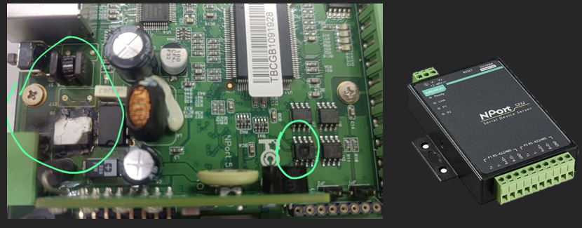
The image shows a PCB of the Moxa NPort 5232 with evident damage to the power supply circuitry and possibly other components.
Damage Analysis
Left area (DC-DC converter or voltage regulator)
- A component (possibly a MOSFET or regulator) is visibly burned and cracked.
- Signs of charring and overheating indicate a severe thermal failure.
- The nearby coil (inductor) also shows signs of overheating, suggesting that the damage occurred in the power conversion stage.
Right area (control or communication circuitry)
- A component (probably an RS-232 or RS-485 communication driver) has a blackened spot on its package, indicating an internal short circuit or overcurrent.
- The damage distribution suggests that the failure in the power supply may have propagated an overload to the communication section (or vice versa).
The connection involves a MOXA NPort 5232 (NON-ISOLATED) communicating with a tracker controller (ANTAI) via RS-485, and the controller is connected to the grounding ring of the photovoltaic plant. The MOXA has been damaged, but the tracker controller has not. This suggests a problem related to potential differences or electromagnetic interference (EMI).
![]()
Possible Causes of Damage to the MOXA NPort 5232
- Potential difference between MOXA GND and tracker controller GND
- The MOXA NPort 5232 is non-isolated, meaning its ground reference is directly connected to the RS-485 communication line.
- In a photovoltaic plant, the controller’s ground connection may have a different potential from that of the MOXA (e.g., if the MOXA is in an isolated cabinet or in another power system with a different potential).
- This potential difference generates compensating currents through the RS-485 bus, which can damage the MOXA circuits.
- Ground loops and parasitic currents
- The controller's ground is connected to the photovoltaic plant's grounding ring, while the MOXA's ground may not be connected to the same ground point.
- A ground loop between these two devices can generate parasitic currents that affect the MOXA, causing overload in its internal circuits.
- Voltage spikes induced by lightning strikes or transients in the network
- If the photovoltaic plant is in an area with high electrical activity (lightning) or has inductive loads connected to the 230V grid, voltage spikes can induce overvoltages in the RS-485 line.
- The tracker controller may have protection against these spikes, but the non-isolated MOXA NPort 5232 does not have a protective barrier.
- Electromagnetic interference (EMI) in the RS-485 wiring
- If the RS-485 cable is near high-power conductors or variable frequency drives, high-energy transient pulses may be induced in the communication.
- This can affect the MOXA first, as its communication electronics are more sensitive than those of the tracker controller.
Solution and Prevention
- Use a MOXA with galvanic isolation
- A model with galvanic isolation on the RS-485 interface (such as the MOXA NPort 5230 or 5232I) would protect against potential differences.
- An external RS-485 isolator can also be used.
- Connect both devices to the same ground reference
- If the MOXA must be isolated from the plant’s ground, it is recommended to use an isolation transformer or a floating power supply.
- If not possible, connect a low-impedance resistor (100Ω - 1kΩ) or a varistor between the grounds to reduce transients.
- Implement transient suppressors (TVS, MOV)
- Place TVS diodes on the RS-485 line to absorb transient overvoltages.
- Use twisted and shielded RS-485 cabling
- Connect the shielding of the cable at a single ground point to avoid current loops.
- Review the grounding topology
- Ensure the MOXA and the controller grounds are equipotential.
Conclusion
The problem seems related to potential differences and lack of isolation in RS-485 communication. The MOXA was damaged because it is more vulnerable to these potential differences, whereas the tracker controller likely has internal protections.
The best solution would be to use a MOXA with galvanic isolation or install an RS-485 isolator between both devices.
Isolated DC-DC Converter
Powering the MOXA NPort 5232 with an isolated DC-DC converter could help mitigate the problem, but it would not completely eliminate the risk of damage if the potential difference still exists on the RS-485 line. Explanation of the effects and limitations of this improvement:
Effect of Powering the MOXA with an Isolated DC-DC Converter:
Advantages
- Eliminates the ground loop in the power supply
- If the MOXA was powered by a source with a common ground reference to the controller, it was creating a compensating current path.
- An isolated DC-DC converter would separate the MOXA’s ground reference, preventing these currents from flowing through the power supply.
- Reduces the likelihood of overcurrent in the power supply
- If transients or spikes in the network were affecting the power source, the isolated DC-DC converter would act as a filter, protecting the MOXA’s internal circuit.
- Improves immunity to electrical noise in the power supply
- A photovoltaic system generates a lot of electromagnetic noise (EMI), especially with inverters and power controllers.
- The isolated power supply helps reduce noise injection into the MOXA.
Limitations and Persistent Risks
- DOES NOT isolate RS-485 communication (where the damage occurred)
- The MOXA is still directly connected to the RS-485 bus, which may be subject to potential differences with respect to the tracker controller.
- If there is a significant potential difference between DATA+ / DATA-, current will continue to flow through the MOXA’s internal circuits, potentially damaging it.
- Transients on the RS-485 line still affect the MOXA
- If the issue arises from overvoltages induced on the RS-485 bus (from lightning, inductive loads, or electrical noise), the DC-DC converter does not protect the communication line, only the power supply.
- The tracker controller remains connected to the photovoltaic plant’s ground, which can create a floating potential on the RS-485 line relative to the MOXA.
- Damage can still occur from electrostatic discharge (ESD) or voltage spikes in RS-485
- The NON-ISOLATED MOXA is more vulnerable to voltage spikes on the RS-485 line, so transient suppressors (TVS or MOV) would still be necessary.
Conclusion and Best Solution
- Powering the MOXA with an isolated DC-DC converter helps, but does not completely solve the problem.
- The real issue remains on the RS-485 line, which is still exposed to potential differences and transients.
- Recommended solution:
- Isolated DC-DC converter to power the MOXA
- Use of an RS-485 isolator (optical or isolation transformer)
- TVS diodes or surge suppressors on RS-485
- Verify that the RS-485 cable shielding is connected at only one end
Common Ground Reference
When referring to a "common ground reference," it mainly relates to the GND reference of the power supply used to energize the equipment. However, in electrical systems, this may also be indirectly related to the grounding (chassis or protective earth), depending on how the equipment is connected.
Differences Between Power Supply GND and Grounding:
- Power Supply GND (Circuit Reference)
- This is the electrical reference point for powering the equipment (e.g., the negative terminal of a 12V or 24V power supply).
- In many cases, this GND is not directly connected to physical ground but only serves to establish the relative voltage level of the internal circuitry.
- If the MOXA and the tracker controller share the same power source, their GND reference is the same.
- Potential issue: If the tracker controller’s GND is connected to the physical ground of the photovoltaic plant and the MOXA’s is not, a potential difference may arise.
- Grounding (Chassis or Protective Ground)
- This is the physical connection to ground (grounding ring of the photovoltaic plant).
- It is primarily used for safety and protection against electrical discharges.
- In some equipment, the power supply GND is floating, while in others, it may be connected to grounding.
- Potential issue: If the MOXA is housed in a cabinet connected to a different ground than the controller, potential differences can generate parasitic currents.
In this specific installation:
- The MOXA and the tracker controller appear to have different GNDs
- The MOXA may be connected to a floating power supply or have a different GND.
- The tracker controller is directly connected to the plant’s ground.
- If the RS-485 line is not isolated, the devices may be at different potentials
- Since the MOXA is not isolated, its communication GND is at the same level as its power GND.
- If the controller has a different ground potential, compensating currents will flow through the RS-485, damaging the MOXA.
Recommended Solution
Case 1:
If you want to keep RS-485 communication non-isolated:
- Ensure that the MOXA and the controller share the same GND reference (i.e., connect the MOXA’s GND to the controller’s GND).
- Avoid ground loops: If the devices are connected to different grounding points, use a 100Ω - 1kΩ resistor between GNDs to dissipate potential differences.
MOXA NPORT 5232          Tracker Controller
   ┌─────┐                    ┌─────┐
   │     │ RS-485   ─────────▶│     │ DATA+
   │     │ RS-485   ─────────▶│     │ DATA-
   │     │                    │     │
   │ GND ├──────[100Ω - 1kΩ]──┤ GND │  ← Parallel resistor
   └─────┘                    └─────┘
- Use surge suppressors (TVS diodes) on RS-485 to protect against transients.
Case 2:
Use an RS-485 Isolator (optimal solution)
- Install an RS-485 isolator between the MOXA and the tracker controller.
- This breaks the ground loop and prevents potential differences from damaging the MOXA.
Case 3:
Power the MOXA with an isolated DC-DC converter
- This helps prevent ground loops through the power supply but does NOT fully protect RS-485 communication.
Conclusion
The key is to ensure that the MOXA and the controller share the same GND reference in RS-485 or use a galvanic isolator in communication. Powering it with an isolated DC-DC converter helps, but does not eliminate the communication risks.
Problem Analysis Based on Ground Connection
The installation has the following grounding configuration:
- The tracker controller
- Its power supply GND is connected to the grounding ring of the photovoltaic plant.
- This means that any equipment connected to this controller, such as the MOXA, could experience potential differences if not referenced to the same ground.
- The electrical panel where the MOXA is installed
- Its power supply is not connected to the grounding ring of the photovoltaic plant.
- This may cause the MOXA’s GND reference to float at a different potential than the tracker controller.
Consequences of This Configuration
Potential differences in the RS-485 line:
- The RS-485 line requires a common GND or galvanic isolation.
- Since the controller is referenced to the plant ground and the MOXA is not, a significant potential difference may develop between them.
- This causes compensating currents to flow through the RS-485 interface, damaging the MOXA transceiver (and possibly its power supply).
Parasitic currents through the communication line:
- If there are electrical storms, nearby inductive loads, or network transients, voltage spikes may travel through the ground and affect the RS-485 interface.
- Since the MOXA is at a different floating potential, it is more vulnerable to these transients.
Possible damage due to electrostatic discharge (ESD) or overvoltage:
- If the tracker controller is in a grounded metal structure and the MOXA is floating, when the RS-485 cables are connected, potential discharges may occur, causing instant damage.
Solutions to Prevent Damage to the MOXA
Option 1: Connect the Electrical Panel GND to the Plant Grounding Ring.
A quick and effective solution if it can be done without causing ground loops.
- Connect the power supply GND of the MOXA to the same grounding ring of the plant.
- This would equalize potentials and prevent parasitic currents in RS-485.
- Possible risk: If the electrical panel has a different ground connection, a ground loop could occur, causing other electrical issues.
Option 2: Use an Isolated DC-DC Converter for the MOXA Power Supply
Helps avoid potential differences in the power supply but does NOT fully protect RS-485.
- It would isolate the MOXA’s power supply, reducing the chance of its GND floating at a different potential than the controller.
- However, RS-485 would still be non-isolated, so issues could persist.
Option 3: Use an RS-485 Isolator (Most Secure Solution)
This is the best solution to prevent potential differences from damaging the MOXA.
- An optical or transformer-based RS-485 isolator would prevent the potential difference between the two devices from flowing through the data line.
- Each device would maintain its ground reference without needing to equalize them.
- Recommended devices:
- Industrial RS-485 isolators (from MOXA, Advantech, Phoenix Contact).
- RS-485 to fiber optic converters for long distances.
Conclusion
Since the tracker controller is referenced to the photovoltaic plant’s ground, but the MOXA is not, this creates a potential difference in RS-485 communication, which likely caused the MOXA’s damage.
Recommended Solutions (priority order):
- RS-485 Isolator → Best option to completely eliminate the problem.
- Connect the electrical panel GND to the plant ground (if it does not cause ground loops).
- Use an isolated DC-DC converter for MOXA power (but does not solve the RS-485 issue).
Implementing the RS-485 isolator will resolve the root cause and prevent future damage.
Recommended Isolators
Replacing the MOXA with a model featuring built-in isolation can be costly. Fortunately, external RS-485 isolators are more affordable and can be integrated into your current system to provide the necessary isolation. Examples include:
RS-485 Isolator by Ewimar, Model: EW-485/1/2/S
Features:
- Provides 1 kV galvanic isolation, ideal for eliminating ground loops and protecting against potential differences.
- Designed for CCTV, access control, and industrial automation applications.
- Functions as a repeater, extending the RS-485 signal and improving communication integrity.
RS-485 Isolator by Ardetem-Sfere, Model: IS 485
Features:
- Provides 2500 V galvanic isolation, ensuring separation between transmitters and receivers in the same RS-485 line.
- Includes built-in bias and termination resistors, suitable for MODBUS and PROFIBUS DP networks.
- LED indicators for transmission and reception, simplifying communication status monitoring.
- DIN rail mounting, compact dimensions 22.5 x 75 x 120 mm.
Industrial RS-485 Isolator by COMMFRONT
Description:
- This industrial device provides isolation and signal repetition for RS-485/RS-422 signals, extending communication distance and protecting against electromagnetic interference.
Features:
- Isolates RS-485/RS-422 groups, preventing interference and protecting against overvoltage.
- Converts RS-485 (2-wire) to RS-422 (4-wire) and vice versa, offering network configuration flexibility.
- Extends RS-485 communication distance, improving signal integrity in extensive installations.
Considerations When Selecting an RS-485 Isolator:
- Isolation Level: Ensure the device provides adequate isolation for your application, typically 1 kV or higher.
- Communication Speed: Check that the isolator supports your RS-485 network’s data rate to avoid bottlenecks.
- Compatibility: Confirm that the isolator is compatible with your system’s voltages and configurations.
- Operating Environment: Consider temperature, humidity, and potential EMI where the isolator will be installed.
Common Mode Voltage Difference in RS-485
The term "common mode voltage difference" refers to an electrical potential difference that may exist between the reference points (GND) of two devices communicating via RS-485.
Problem Explanation
Common Mode vs. Differential Mode In differential communication like RS-485, data is transmitted as the voltage difference between two lines: DATA+ and DATA-. Ideally, both devices should share a common ground reference, but in practice, they may be at different ground potentials.
Common Mode Voltage Difference If the GND of the MOXA and the GND of the tracker controller are at different electrical potentials (due to being connected to separate physical grounds), this creates a common mode voltage in RS-485 communication. This common mode voltage superimposes itself onto the differential signal and can distort communication, generate errors, or even damage the RS-485 transceivers.
How Does Common Mode Voltage Difference Affect Communication?
- Data Transmission Errors
- RS-485 can tolerate up to ±7V of common mode voltage under normal conditions, but exceeding this limit can make communication erratic.
- Parasitic Currents Through the RS-485 Line
- If there is a significant ground difference, unwanted currents may circulate through the data cable, damaging transceivers.
- Failures in Communication Circuits
- If the potential difference is high, it can induce voltage spikes that damage RS-485 circuits, as seen with the MOXA device.
Solutions to Eliminate Common Mode Voltage Difference
RS-485 Optical Isolator
- An optical RS-485 isolator breaks the direct electrical connection between devices, allowing each device to maintain its own ground reference without interference.
- This eliminates common mode voltage, protecting communication circuits.
Connecting Devices to the Same Ground Reference
- If possible, connect the GND of the MOXA to the GND of the tracker controller using a 100Ω - 1kΩ resistor to reduce the potential difference.
Using Transient Voltage Suppressors (TVS) on the RS-485 Line
- TVS diodes protect against voltage spikes induced in communication.
Using Shielded RS-485 Cables with Grounding at a Single Point
- This prevents electromagnetic interference and potential differences over long distances.
Conclusion
The common mode voltage difference is a critical issue in RS-485 when devices are connected to different grounds. An optical RS-485 isolator is the best solution because it eliminates this problem without requiring modifications to the photovoltaic plant’s grounding system.
Function of the Resistance Between the GNDs of the MOXA and the Tracker Controller
Connecting the GND of the MOXA to the GND of the tracker controller through a 100Ω - 1kΩ resistor aims to reduce the common mode voltage difference, preventing unwanted currents from flowing through the RS-485 communication line. Let’s break it down:
What Problem Are We Trying to Avoid?
When two devices have different ground references, potential differences between their GNDs can arise. This can cause:
- Parasitic currents through RS-485, which may damage the MOXA transceiver.
- Electrical noise and interference affecting communication.
- Data transmission errors due to floating voltages.
How Does the Resistor Help?
By placing a series resistor between the GNDs, we create a controlled path to balance ground potentials without allowing harmful currents to flow.
Benefits of the parallel resistor between GNDs:
- Allows for gradual voltage compensation between devices.
- Without the resistor, if there is a large potential difference between grounds, connecting RS-485 cables could cause a sudden current spike, damaging the MOXA.
- The resistor limits and dissipates this current in a controlled manner.
Prevents constant current flow through RS-485.
- If the GNDs are directly connected with a thick cable, unwanted currents may circulate between them.
- The resistor acts as a filter, allowing potential differences to compensate without creating significant current.
Reduces common mode voltage in communication.
- The resistor helps keep potentials closer, decreasing common mode voltage that could disrupt data transmission.
Why Use Values Between 100Ω and 1kΩ?
- Less than 100Ω → The resistor is too low, allowing excessive current flow, which may create ground loops and interfere with communication.
- More than 1kΩ → The resistor is too high and does not sufficiently balance GND potentials.
100Ω - 1kΩ is an ideal compromise:
- Low enough to allow voltage compensation.
- High enough to prevent harmful current circulation.
Conclusion
- If you do not want to replace the MOXA or use an RS-485 isolator, connecting the MOXA’s GND to the tracker controller’s GND with a 100Ω - 1kΩ resistor can help reduce potential differences and improve communication reliability.
- However, the best solution remains using an RS-485 isolator, as it completely eliminates this issue.
Is it Better to Use an RS-485 Optical Isolator or Connect GNDs with a Resistor?
It depends on the magnitude of the problem and the level of security you need. Let’s compare both solutions:
Option 1:
Connecting GNDs with a Resistor (100Ω - 1kΩ).
Advantages:
- Simple and cost-effective solution without additional hardware.
- Reduces potential difference between devices, minimizing common mode voltage.
- Sufficient if the potential difference between GNDs is small (<2-3V).
Disadvantages:
- Does not completely isolate the system, so high voltage spikes or lightning strikes can still damage the MOXA.
- If the potential difference between GNDs is high (>5V), parasitic currents will still flow, affecting communication and potentially damaging the RS-485 transceiver.
- Does not protect against electromagnetic interference (EMI), which is common in photovoltaic plants.
When to Use This Solution?
- If GNDs do not have a significant potential difference.
- If you need a quick and low-cost solution.
- If communication is stable and error-free.
Option 2:
Using an RS-485 Optical Isolator.
Advantages:
- Completely eliminates potential differences, as there is no direct electrical connection between devices.
- Protection against transients and overvoltages, such as lightning strikes or power grid noise.
- Improves immunity to electromagnetic interference (EMI) in industrial environments and photovoltaic plants.
- Prevents damage to MOXA and other equipment by eliminating current circulation through the RS-485 bus.
Disadvantages:
- Higher cost than a simple resistor.
- Requires additional power supply, as RS-485 isolators generally need power on both sides of the isolation.
- Slightly more complex installation but still easy to implement.
When to Use This Solution?
- If GNDs have a potential difference greater than 5V.
- If you have had recurring failures in MOXA.
- If the environment has electrical noise, lightning, or inductive loads that may induce transients in the communication line.
- If you want a definitive solution to protect RS-485 communication.
Conclusion: Which One to Choose?
- If the potential difference between GNDs is low (<2-3V) and you need a quick and cost-effective solution, you can try the 100Ω - 1kΩ resistor.
- If the potential difference is high (>5V) or if MOXA continues to fail due to electrical discharges or noise, the RS-485 optical isolator is the best option.
In photovoltaic plants, where potential differences and transients are common, the RS-485 isolator is the best investment to avoid failures over time.
Is an RS-485 Isolator Better Than an RS-485 Surge Protector?
It depends on the type of problem you are facing. Both devices protect the RS-485 line but work differently and address different issues. Let’s compare them:
Option 1:
Using an RS-485 Surge Protector.
An RS-485 surge protector (TVS, MOV, or gas discharge tube - GDT) is designed to absorb transient voltage spikes on the RS-485 line.
Advantages:
- Protects against transient overvoltages caused by lightning strikes, inductive load switching, or power grid surges.
- Does not require an external power supply.
- Easy to install and cost-effective.
- Does not affect communication speed or integrity.
Disadvantages:
- Does not protect against potential differences between GNDs.
- Does not eliminate common mode currents, which are the primary cause of damage in this case.
- Does not electrically isolate MOXA from the tracker controller.
When to Use an RS-485 Surge Protector?
- If the main problem is exposure to lightning strikes, voltage spikes, or electrical noise in the power grid.
- If communication is working well and you only want to prevent damage from transient overvoltages.
- If the RS-485 cable run is long and exposed to external interference.
Option 2:
Using an RS-485 Isolator.
An RS-485 isolator breaks the electrical connection between devices, eliminating potential differences and parasitic currents.
Advantages:
- Fully isolates MOXA from the tracker controller.
- Eliminates potential differences between GNDs, preventing harmful currents.
- Protects against common mode noise and electromagnetic interference (EMI).
- Prevents communication failures caused by ground loops.
Disadvantages:
- Requires power on both sides.
- More expensive than a surge protector.
- If the issue is only transient voltage spikes and not potential differences, it may be an unnecessary solution.
When to Use an RS-485 Isolator?
- If the main problem is a potential difference between the GNDs of the devices.
- If MOXA has already been damaged due to ground differences.
- If the environment has significant electromagnetic noise and RS-485 communication is unstable.
Which One to Choose in This Case?
If the problem is transient overvoltages (lightning strikes, switching surges in the electrical network):
- An RS-485 surge protector is sufficient.
If the problem is a potential difference between MOXA and the tracker controller:
- The RS-485 isolator is the best solution.
If you suspect both problems (overvoltages and potential differences):
- Use an RS-485 isolator + a surge protector for maximum protection.
Final Recommendation
Since your MOXA has already been damaged, this suggests that the problem is likely a potential difference between GNDs. Thus, the RS-485 isolator is the best option to prevent future occurrences.
If there is also a risk of voltage spikes from lightning strikes in the photovoltaic installation, you can add an RS-485 surge protector alongside the isolator.
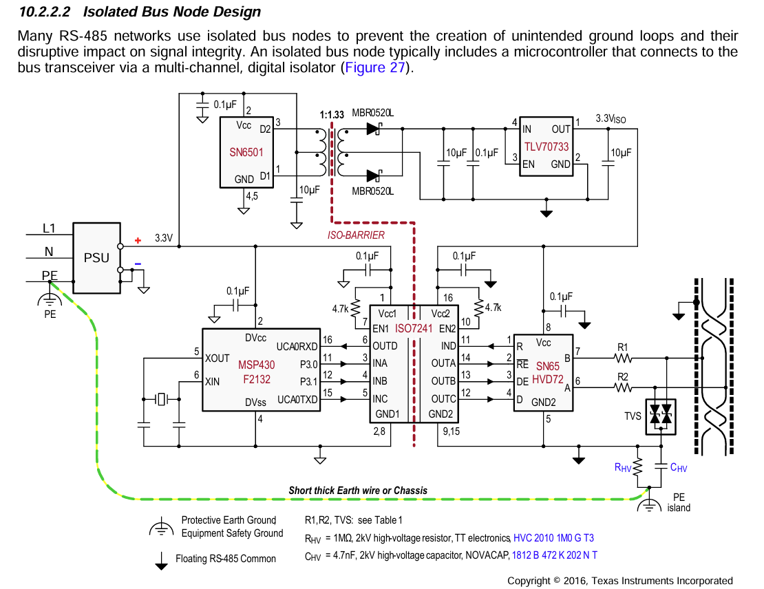
Internal structure of an RS485 bus isolator